
If you own Lake Shore temperature instrumentation, you might receive a message on your screen of one of the following.
T. Over, T.Under, S.Over, S.Under
Explanation of sensor value messages
These messages indicate that the instrument cannot display a valid temperature because the sensor value exhibits one of these conditions.
T. Over: the sensor value is beyond the highest temperature point on the curve assigned to the input
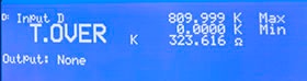
- For NTC devices, this means the sensor value is lower than the value shown in the highest curve breakpoint
- For PTC devices, this means the sensor value is higher than the value shown in the highest curve breakpoint
T. Under: the sensor value is beyond the lowest temperature point on the curve assigned to the input
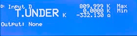
- For NTC devices, this means the sensor value is higher than the value shown in the highest curve breakpoint
- For PTC devices, this means the sensor value is lower than the value shown in the highest curve breakpoint
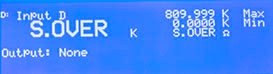
S. Over: the sensor value is greater than the physical limit of the input
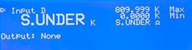
S. Under: the sensor value is negative
Troubleshooting sensor value messages
Troubleshooting T.Over or T.Under
Look at the front panel sensor reading.
- If the sensor reading looks reasonable, then check the curve that you selected. You may have inadvertently selected the wrong curve for the sensor you are using.
- If the sensor reading is not out of range (S.Over, S.Under) but is not what it should be, then verify the sensor setup.
- If the front panel displays a negative resistance, then the direction (+/-) of either the voltage or the current leads are reversed.
- If the reading is near zero (in either ohms or volts) then the sensor might be shorted, or the current leads might be broken.
Troubleshooting S.Over or S.Under
Look at the front panel sensor reading.
- If the reading is S.Over, then either the wrong range is chosen, or the sensor is open, or the voltage leads are broken.
Troubleshooting the sensor
To test your sensor, you can use a handheld multimeter. Here is a procedure to do this:
Using a digital multimeter that can measure resistance in the MΩ range, perform the following measurements:
- Pin 1 to Pin 2 – Result should be a low resistance determined by the gauge and length or wire
- Pin 4 to Pin 5 – Result should match the measured resistance found in Step 1
- Place the COM probe on Pin 1 and the positive probe (or, V Ω probe) on Pin 5.
For a diode sensor, the resistance should read somewhere between 3 to 7 MΩ.
For a platinum or Cernox™ (NTCRTD) sensor, the reading will depend on the resistance of the sensor at the current temperature - Reverse the leads
For a diode sensor, the reading should be infinite (open).
For a platinum or Cernox™ (NTCRTD) sensor, the reading will depend on the resistance of the sensor at the current temperature and should match the reading in Step 3.
If you have any further questions concerning these error messages, please feel free to ask them in the comments or contact our support department.
Also, if you liked this tip and would like to see other tips on here as well, we hope you will let us know what you would like to see covered.