DC Circuit Types
Many people forget that when you add instrumentation to your device under test (DUT), it becomes part of the circuit. Choosing the wrong circuit setup can cause unintended measurement problems.
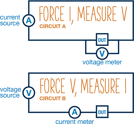
Consider the simple measurement circuits below, where the DUT could be characterized by two different DC circuits. In Circuit A, the current is sourced and the voltage is measured. In Circuit B, voltage is sourced and current is measured. For most DUT resistances, either circuit will give approximately the same answer. But the story changes at the extremes of DUT resistance values.
Dealing with Extremes
When the DUT resistance is very high, measuring the voltage directly across the DUT, as in Circuit A, is difficult because the volt meter input resistance is placed in parallel with the DUT resistance. This causes a significant portion of the current to pass through the meter, reducing the DUT current and resulting in voltage error.
Changing the setup to Circuit B resolves this problem but may require a very good current meter to measure the very low current values resulting from the high DUT resistance. In this case, a practical solution is to switch to an AC source coupled to a lock-in amplifier to avoid the “1/f” noise.
Low resistances can also present measurement challenges. For these devices, Circuit B requires a high current to increase the voltage drop to a measurable quantity; unfortunately, this maximizes the device internal heating, changing the resistance. Therefore, Circuit A is a better choice for low-resistance devices.
Download our free paper to learn other mistakes to avoid in electronic device measurement: